Transducer

Insertion Loss

Measurement of Insertion Loss

Insertion loss characterizes the sensitivity of a transducer and is defined as:

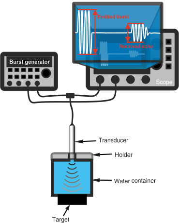
To measure a transducer's insertion loss, an ultrasonic burst is emitted. The same transducer receives an echo from a plane target that is perpendicular to the beam and has an acoustic impedance significantly different from the liquid used for transmission. The voltage ratio between the echo and the emitted burst, expressed in logarithmic form, is the Insertion Loss (IL).

Signal Processing's transducers typically have an IL between 6 and 20 dB, depending on the type of transducer.

Required equipment:

  • Burst generator
  • Amplifier (optional)
  • Oscilloscope
  • Two 50 Ω coaxial cables + 1 T-connector
  • Water container with transducer holder
  • Target (stainless steel recommended)

Burst Generator Setup

  • Burst generation mode
  • Amplitude: 5 Vpp on 50 Ω
  • 4 cycles
  • Interval between bursts: 10,000 cycles

Connect the transducer, burst generator, and oscilloscope as shown in the figure.

Caution:

Verify that the burst generator can handle the connection of a very low impedance (<50 Ω) for an extended period to avoid damage.

Measurement Procedure

  • Ensure good coupling between transducer and liquid (no air bubbles).
  • Ensure transducer is perpendicular to the target for maximum echo voltage.
  • Measure the voltage of the emitted burst.
  • Measure the voltage of the received echo.
  • Calculate the Insertion Loss.

Important Notes:

The distance between the transducer and the target should be sufficient to avoid near-field disturbances but short enough to capture all emitted energy. The target thickness also matters to prevent interference from reflections off the far surface.

To minimize interference from the second echo, use a target with high acoustic impedance relative to the liquid.