Transducer

Theoretical aspects

The ultrasonic field

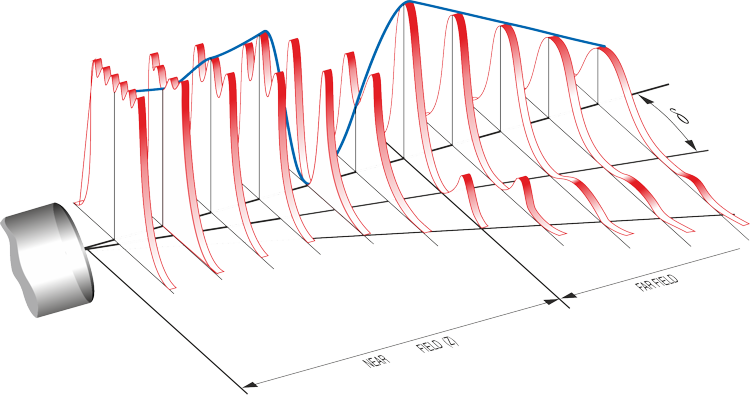
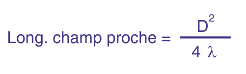
In Doppler echography, the goal is not to use a plain longitudinal wave, but rather an ultrasonic beam that is as thin as possible throughout the measurement depth. The geometry of the acoustic field is governed by the diameter D of the emitter and the wavelength λ of the ultrasonic waves, which is equal to the ratio of the sound velocity in the analyzed medium to the emitting frequency. The typical shape of the ultrasonic field is illustrated in the figures below, which show two particular zones.

Typical ultrasonic beam showing near and far field zones
Equation for near field length of ultrasonic transducer

The near field

The region located close to the transducer surface is called the near field. In this zone, the acoustic field is essentially cylindrical, with a diameter slightly smaller than that of the emitter. The intensity of the acoustic waves oscillates along the axis of the transducer. If the distances of these oscillations are much smaller than the dimensions of the measured volumes, they do not significantly affect Doppler measurements.

However, if the length of the near field is large, the oscillations of the acoustic waves may affect measurements. Therefore, it is generally not recommended to perform measurements too close to the transducer in such cases. The length of the near field is defined by the position of the last maximum of the acoustic intensity.

The far field

The region beyond the near field is called the far field. In this zone, the intensity of the acoustic waves along the axis decreases approximately with the inverse square of the distance from the transducer, and small radial oscillations appear. Most of the acoustic energy is contained in a cone, whose half-angle θ is characterized by the equation below.

Equation for divergence of ultrasonic beam
Chart of ultrasonic beam divergence vs diameter and frequency

The divergence of the ultrasonic beam depends on the diameter of the piezo element and the emitting frequency. A compromise between these two parameters is usually necessary to achieve the thinnest beam possible at a defined distance. The chart above shows the theoretical half-angle θ for a sound velocity of 1500 m/s (water) as a function of the piezo diameter and frequency. Note that a higher frequency improves axial resolution but may also increase attenuation of the ultrasonic waves.

Practical considerations

The equations and curves above are based on the computation of the acoustic pressure at specific points in the field. Ultrasonic Doppler Velocimetry (UDV) analyzes backscattered energy, meaning that the acoustic pressure at a point alone is insufficient to define the sampling volume.

The width of the sampling volume can be determined by measuring the intensity of an echo generated by a small spherical target. Such measurements are available for all our transducers and are displayed in the transducer selection guide.

Measured ultrasonic field showing sampling volume