Technique

Faq

Frequently asked questions

On UDV applications...

How to install ultrasonic transducers?

The main important point is to insure a good coupling between the transducer and the liquid. Any gas interface is not allowed because gas has a very low acoustic impedance and therefore reflects all the ultrasonic energy.

The best coupling is realized when the transducer is immersed in the liquid. All Signal Processing's transducers can be completely submerged in any liquid which is not chemically aggressive. The housing of the transducer is made of stainless steel and the front surface is made of epoxy. Other material for the housing can be also available.

When it is not possible to immerse the transducer and a solid wall has to be crossed, an ultrasonic coupling gel is used.

Normally the transducers are delivered with a standard cable of 1.5 meter, but longer cable can be used. The only requirement is to use a 50 ohm cable, like any RG174 or RG58 cable. Using a cable longer than 10 meters can induce some noise in the measurement and some loss in sensitivity.

Is it possible to apply UDV in gas?

Unfortunately not. There are two main reasons for this. The attenuation of ultrasonic waves is very strong at the frequencies used and it is very seldom to find particles of compatible dimensions that can follow the gas flow. Nevertheless it is possible to measure the velocity of a solid surface if a small gap exists between the transducer and the moving surface (in the order of few centimeters).

Is it possible to measure mud flows?

Ultrasonic Doppler velocimetry is almost the unique technique that is capable to measure in real time a velocity profile in mud. Despite the high degree of attenuation of mud, successful measurement can be realized up to concentration of sand in the order of 30%.

Is it possible to measure blood flows?

Ultrasonic Doppler velocimetry was originally developed for medical applications. Our ultrasonic velocimeters have been used for many years in the medical field to investigate blood flows in the venous and arterial system. Signal Processing has obtained the EN46001 certification in order to help our customers to use our equipment in the medical field.


On DOP features...

What about the spatial resolution?

Two types of resolution have to be considered. The first one concerns the dimensions of the sampling volume, which is the volume from which particles contribute to the measurement of a single velocity value. Its lateral dimension (perpendicular to the ultrasonic field axis) is determined by the shape of the ultrasonic field. Typical values are from few millimeters to few centimeters.

The axial dimension of the sampling volume is fixed by the duration of the emitted burst and the bandwidth of the receiver. Typical values are in the order of tenth of millimeters to few millimeters.

The other resolution concerns the minimum distance between two adjacent gates. This distance is determined by the sampling rate of the incoming echoes. Three different situations may appear:

  • The distance between gates is lower than the thickness of the sampling volume.

    In such a case the sampling volumes overlapped each other.
  • The distance between gates is equal to the thickness of the sampling volume.

    In such a case the sampling volumes are contiguous.
  • The distance between gates is greater than the thickness of the sampling volume. In such a case a dead zone exists between each gate, zone from which no information is captured and collected by the velocimeter.

What about the velocity range and resolution?

The velocity range is defined by the Doppler equation, which involved three parameters, the emitting frequency, the pulse repetition frequency and the sound velocity in the liquid. By playing with the first two parameters it is possible to cover a wide range of velocities, from less than 1 mm/s to few m/s.

Both positive and negative velocities can be measured simultaneously. Moreover, an original technique allows to distribute unequally the range of positive and negative velocities.

All velocity values are given in a signed byte format, which fixes the velocity resolution to 1/128 of the maximum scale. In order to increase the velocity resolution, the maximum velocity scale can be reduced by the velocity scale factor.

Which velocity component is measured?

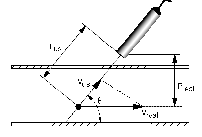
The velocity component measured by the velocimeter is always the component in the direction of the ultrasonic beam (Vus). When the direction of the real velocity is known, the velocimeter can automatically compute the real velocity value(Vreal) by using the value of the Doppler angle. In such a case the depth values displayed by the velocimeter are the depths perpendicular to the velocity direction (Preal).

How to choose an emitting frequency?

The emitting frequency is directly linked to the resolution. So, in most situation, it is advantageous to select the highest emitting frequency as possible. Unfortunately, two factors limit the available choice. The maximum velocity that should be measured (see the Doppler equation) and the attenuation of the ultrasonic waves when they travel through the liquid and the wall material that have to be crossed.

The attenuation of the ultrasonic waves depends a lot on the emitting frequency and on the type of liquid. High ultrasonic frequencies are much more attenuated than low frequencies.

How is the flow rate computed?

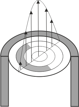
The velocimeter can compute automatically the flow rate when a measuring section is defined. The flow rate is computed by integrating the velocity profile between two user's limits, placed on the velocity profile. These two limits define a section, which is assumed to be circular. The flow rate can be displayed in real time on the screen.

How fast is a velocity profile measured?

Velocity profiles can be measured up to a rate of around 500-300 Hz. But this is not always the case. The acquisition time of a complete profile depends on three parameters:

  • The sound velocity in the liquid
  • The maximum depth at which measurements have to be done. Once has to wait until an emitted ultrasonic burst travel to desired depth and comes back to the transducer. The maximum time allowed is fixed by the pulsed repetition frequency (PRF).
  • The number of ultrasonic emissions used to estimate the velocities in the gates. The variance of the measured values is influenced by this number. As velocities are nothing else than first moment order of statistical processes, having more realizations of these processes reduce the variance of the estimated values.

Is it possible to synchronize the velocimeter?

Yes, the velocimeter can be synchronized to an external event by using its trigger input. The trigger signal can be a low or a high logic level (0 or 5 Volt) on the external trigger input or a keyboard action. Moreover after a trigger signal has been accepted, the velocimeter can wait a user's defined lapse of time and then start the acquisition of data profiles. The delay between the trigger signal and the acknowledge of the trigger signal can be as low as few microseconds.

The smart trigger interface allows to define complex acquisition sequences, with automatic record procedures.

How close to the transducer a measurement can be realized?

Normally the same transducer is used to emit the ultrasonic burst and to receive echoes. This implies that during the emission it is not possible to receive any echoes. Moreover, just after the emission, the transducer has to dissipate the amount of energy that hasn't been sent into the liquid. Only after this dissipation it will be able to sense the very small level of the ultrasonic echoes.

The position of the first measurable gate depends therefore on the emitting frequency, the burst length and the size of the active element that generates the ultrasonic waves. For instance, at 8 MHz, the first measuring gate can be placed at around 3 mm from the surface of the transducer, which value should be considered as a minimum value.

How are measured data recorded?

All displayed data profiles can be recorded to a file in a binary or ASCII format. This means that when both the velocity profile and the Doppler energy profile are measured and displayed, both data profiles will be recorded. In order to offer the maximum flexibility, both format can be selected at the same time, which produces two files. Each recorded file contains a user's reserved area for the introduction of comments.

The binary format does not record only measured data but also record all the values of the functioning parameters. This allows the execution of any kind of post-processing methods on the original data, and also allows to replay directly in UDOP software any recorded data file.

An accurate time stamp, the flow rate associated to the velocity profile, the identification of the connected channel and the trigger sequence are attached also to all recorded data profile.

How many transducers can be connected to the velocimeter?

Up to 10 different transducers can be connected to the DOP3010 and 4 to the DOP4000.

During the acquisition process in multiplexer mode, the multiplexer switches from one channel to the other after the measurement of a user's defined number of data profiles. As all the channels are totally independent, each channel can accept different probes and different set of parameters or settings, such as different emitting frequencies, PRF, etc...


On UDV technique...

How does pulsed Doppler ultrasound work?

The working principle of the DOP ultrasonic velocimeter is to detect and process many ultrasonic echoes issue from pulses reflected by micro particles contained in a flowing liquid. A single transducer emits the ultrasonic pulses and receives the echoes. By sampling the incoming echoes at the same time relative to the emission of the pulses, the variation of the positions of scatters are measured and therefore their velocities. The measurement of the time lapse between the emission and the reception of the pulse gives the position of the particles.

More information ....

How is the velocity computed?

The measurement of the velocity is based on the estimation of the mean phase shift of successive echoes coming from a defined depth. The algorithm used is based on the random statistical nature of each echo. The algorithm assumes that the statistical properties of all collected echoes used in the computation of the mean phase shift are stationary. This allows to transform temporal average into spatial average and to consider all processes stationary.

As the inverse Fourier transform of the probability density function of a stationary process is equal to the auto-correlation function, the algorithm computes the auto-correlation of the Doppler echoes. The Doppler frequency (Fd) is then computed, and finally the velocity is extracted from Doppler equation:

where (Fe) is the emitted ultrasonic frequency and (C) is the sound speed in the liquid.

The above equation is valid for bi-directional flows having an identical range for the positive and negative velocities. Our velocimeter allows to select a different range for the positive and negative velocities. This allows to measure higher velocity than the above defined value, up to two times, without loss of information concerning the direction of the flow.

Moreover, we have developed a method that extend measuring velocity range by using an automatic correction of the aliasing.

Which velocity component is measured?

The velocity component measured by the velocimeter is always the component in the direction of the ultrasonic beam. When the direction of the real velocity is known, the velocimeter can automatically compute the real velocity value by using the value of the Doppler angle.

What does aliasing mean?

Aliasing is a phenomena that appears when an analog signal is sampled at a frequency which is lower than the half of its maximum frequency. When such a situation appears all the frequencies above the half of the sampling frequency, known as the Nyquist frequency, are back folded in the low frequency region. This phenomena is called aliasing.

To avoid aliasing the analog signal should be filtered before sampling in order to remove all the frequencies above the Nyquist limit. In pulsed Doppler ultrasound velocimetry the sampling frequency is equal to the pulsed repetition frequency (PRF). The pulsed nature of the ultrasonic emission implies that only samples are available. This means that the aliasing phenomena can not be removed, or filtered and may therefore appears.

An easy way to check the presence of aliasing is to examine the evolution of the measured Doppler frequency when the pulsed repetition frequency is changed.

We have developed new methods and techniques that overcomes the aliasing limitation and therefore extends the measuring velocity range.

How small is the spatial resolution can be?

In ultrasonic Doppler velocimetry, the shape and lateral sizes of the sampling volumes (measured perpendicularly to the ultrasonic beam axis) are defined by the geometry of the ultrasonic beam. The longitudinal size of the sampling volumes is defined by the burst length and/or the bandwidth of the electronic receiving unit. As the number of the emitted cycles can be changed, the user can adapt the longitudinal resolution to the application.

The resolution is defined as the distance between the center of adjacent sampling volumes. The very fast processing capabilities of the DOP instrument allow a minimum distance between adjacent gates to be as low as around 0.1 mm in water.

What are the differences between UDV and Laser Doppler techniques?

The main differences between Laser Doppler velocimetry and ultrasonic Doppler velocimetry can be summarized as followed:

  • LDV measures the velocity component perpendicular to the axis of the light beam while UDV measures the component which is in the direction of the axis of the ultrasonic beam.
  • LDV measures the velocity of a single particle. UDV measures the average velocities of a great number of scatters simultaneously and gives therefore the mean value of all the particles present in the sampling volume.
  • The maximum velocity is limited in UDV, not in LDV
  • LDV can not be applied when the liquid contains to many particles, but UDV can.
  • LDV can not be applied in non transparent liquid, but UDV can.
  • UDV gives a complete velocity profile, LDV not.

How safe is ultrasonic Doppler velocimetry?

Ultrasonic Doppler velocimetry is a safe technique when applied correctly. The mean ultrasonic power is low, in the order of few milliwatts. The maximum instantaneous power, which is in the order of tens of watts during the emission of the burst, is most of the time not enough to generate cavitation. The only noticed effect is a small local increase of the temperature of the medium under investigation.

How many transducers can be connected to the instrument?

Up to 10 different transducers for the DOP3010 and up to 4 transducers for the DOP4000 can be connected. For both instruments a sequential acquisition mode is available. The DOP4000 offers the capability to measure simultaneously profiles from all its channels.

The user can define the functioning parameters (emitting frequency, PRF, amplification, number of gates,...) for each transducer. The instrument switches automatically from one transducer to the other after the acquisition of a user's defined number of profiles in sequential mode.

What kind of data can be measured with UDV?

Signal Processing's Velocimeters can measure and record not only velocity profiles but also the echoes profiles, the Doppler energy, the flow rate, the power spectrum and much more.

Moreover, it can record raw data (I and Q signals) for further analysis.

How big can be the concentration of particles?

Ultrasonic Doppler Velocimetry is almost the unique technique that is capable to measure in real time a velocity profile in liquids containing a great number of particles, like mud. For instance, successful measurements can be obtained in concentrations in the order of 30% for mud and more than 50% in blood.